
Page 122 - Academic Press Encyclopedia of Physical Science and Technology 3rd Analytical Chemistry
P. 122
P1: GLQ/LSK P2: FQP Final Pages
Encyclopedia of Physical Science and Technology EN005E-212 June 15, 2001 20:32
Electron Spin Resonance 333
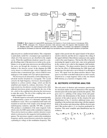
FIGURE 2 Block diagram of a typical ESR spectrometer. KLY, klystron or Gunn diode source of microwaves; ISOL,
isolator; ATTEN, attenuator; Circ, three-port circulator; CAV, resonant cavity; M, magnetic field modulation coils;
XL, detector crystal; PSD, phase-sensitive detector; and OSC, oscillator. The double lines represent a waveguide
connecting the microwave components, and the single line represents a cable connecting the electronic components.
adjacent port in a unidirectional fashion. This component signal is then passed into the signal channel of the phase-
is particularly useful for a resonance-type experiment in sensitive detector, and this device compares the coding of
which all of the microwaves are absorbed in the sample the signal with that of the reference and passes only signals
cavity. When this equilibrium situation is upset by a sam- coded at the same frequency. This has the effect of greatly
ple absorbing some of the microwaves in the cavity, an im- increasing the signal-to-noise ratio, since noise generated
balance is set up and some microwaves are reflected from in the system is not coded at the magnetic field modula-
the cavity out through the circulator in a unidirectional tion frequency. The phase-sensitive detection procedure
fashion to the detector crystal. In the diagram the ESR also has the effect of differentiating the ESR signal and
cavity shown is a reflection type, which is typically more producing a first-derivative curve instead of an absorption
sensitive than a transmission type, which would be more curve. The signal from the phase-sensitive detector then
analogous to the sample cell of an optical spectrometer. goes to a recorder or another readout device and is usually
The microwaves are detected by a semiconducting crys- referenced to a swept magnetic field so that one obtains
tal diode rectifier mounted in a waveguide. This crystal ESR intensity as a function of magnetic field.
converts the high-frequency microwave electromagnetic
radiation to a direct current voltage, which can then be III. ISOTROPIC HYPERFINE ANALYSIS
amplified and treated by ordinary electronics. For opti-
mum sensitivity, the detector crystal is biased with a little The real power of electron spin resonance spectroscopy
reflected microwave power controlled by the size of the for structural studies is due to interaction of the unpaired
iris, which is the coupling hole allowing the microwaves electron spin with nuclear spins in molecular species. This
to enter the cavity. The size of this coupling hole can be gives rise to a splitting of the energy levels and gener-
simply changed with a screw tip. ally allows the determination of the atomic or molecular
Sothatthesignal-to-noiseratiocanbeincreasedgreatly, structure of the radical species. In this situation the spin
by approximately a factor of a thousand, magnetic field Hamiltonian of Eq. (1) involves additional terms corre-
modulation is used. This is accomplished with small coils sponding to the nuclear spin interacting with the magnetic
mounted on each side of the sample cavity through which field, to the nuclear spin interacting with the electron spin,
radiofrequency radiation, typically 100 kHz, is passed. and, if the nuclear spin is ≥1, to a nuclear quadrupole in-
This produces a modulation of the static magnetic field, teraction. This more complete spin Hamiltonian may be
which codes the ESR signal at this modulation frequency. written as
Then a device known as a phase-sensitive detector is used,
which is referenced to this magnetic field modulation fre- spin = βH · g · S + hS · A n · I n − g n β n H · I n
quency. The microwave signal is coded at this modulation n n
frequency, and the crystal detector converts the signal into + h I n · Q n · I n . (2)
a pulsating dc voltage at this modulation frequency. This n