
Page 208 - Academic Press Encyclopedia of Physical Science and Technology 3rd Analytical Chemistry
P. 208
P1: ZCK/MBQ P2: GQT Final Pages
Encyclopedia of Physical Science and Technology EN008B-382 June 30, 2001 18:58
Liquid Chromatography 675
head reciprocating pumps have been developed so that the
mobile phase is always being pumped out while the other
piston(s) are refilling. A pulse dampener is usually not
required for these pumps unless very sensitive detector
settings are used. Commercial pulse dampers such as a
coiled flattened tube or a diaphragm unit are available.
They add dead volume to the system, however, which is
undesirable when changing solvents. Some pumps have ti-
tanium not stainless steel all wetted parts for better buffer
salt compatibility. Most pumps permit external washing
of the pump heads without disassembly to eliminate salt
buildup.
C. Injector
In liquid chromatography, introduction of the sample ide-
ally on the column or very close to it is important to
minimize sample diffusion and band broadening. Sample
sizes are small, ∼5–100 µl, with 20 µl being a common
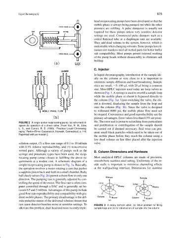
size. Most HPLC injectors used today are loop valves as
shown in Fig. 3. A syringe is used to overfill a sample loop
while the mobile phase or eluent is bypassed directly to
the column (Fig. 3a). Upon switching the valve, the elu-
ent is diverted, displacing the sample from the loop and
onto the column (Fig. 3b). Since the valve is designed
to withstand 6000 psi, the mobile phase flow need not
be stopped. Convenience and good reproducibility are the
primary advantages. Error values less than 0.5% are possi-
ble. The rotor seal is prone to scratching from particulates
FIGURE 2 A single-piston reciprocating pump. (a) schematic di-
agram (b) operation of a check valve. [From Yost, R. W., Ettre, and prefiltration or centrifugation of the sample should
L. S., and Conlon, R. D. (1980). “Practical Liquid Chromatog- be carried out if deemed necessary. Seal wear can gen-
raphy,” Perkin–Elmer Corporation, Norwalk, Connecticut, p. 146. erate small black particles which need to be taken out of
Reprinted with permission.]
the mobile phase before they reach the column using a
low dead volume on-line filter placed after the injection
solution output, (3) a flow rate range of 0.1 to 10 ml/min valve.
with 0.5% relative reproducibility, and (4) noncorrosive
wetted parts. Although a variety of pumps such as the
D. Column Dimensions and Hardware
syringe and pneumatic types have been used, the recip-
rocating pump comes closest to fulfilling the above re- Most analytical HPLC columns are made of precision,
quirements at a modest cost. A schematic diagram of a smooth-bore stainless steel tubing. Uniformity of the in-
simple reciprocating pump is shown in Fig. 2a. Basically, side walls is important to minimize channeling effects
the operation involves a motor rotating a cam that pushes at the wall/packing interface. Dimensions for stainless
a sapphire piston back and forth in a small chamber. Ruby
ball check valves (Fig. 2b) permit solvent flow in only one
direction. The pumping rate is generally adjusted by con-
trolling the speed of the motor. The flow rate is often com-
puter controlled through a DAC and is generally set be-
tween 0.5 and 3 ml/min. Advantages of this pump include
good flow-rate reproducibility and compatibility with gra-
dient mobile phases. The primary disadvantage is the def-
inite pulselike nature of the delivered solution stream that
can cause detector baseline noise at sensitive settings. To FIGURE 3 A rotary sample valve. (a) Valve position for filling
alleviate this problem, dual-head and more recently triple- sample loop and (b) for introduction of sample into the column.