
Page 160 - Academic Press Encyclopedia of Physical Science and Technology 3rd Polymer
P. 160
P1: GPB/GLT P2: GQT Final Pages
Encyclopedia of Physical Science and Technology en012f-594 July 26, 2001 11:9
668 Polymers, Ferroelectric
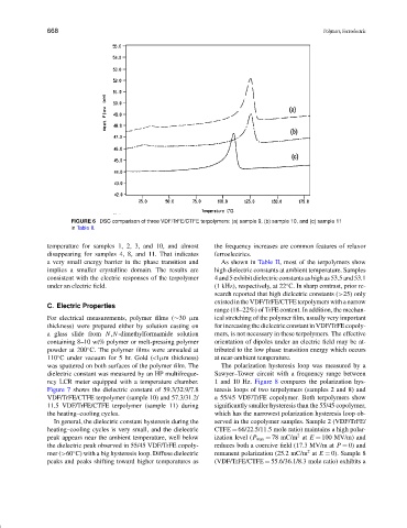
FIGURE 6 DSC comparison of three VDF/TrFE/CTFE terpolymers: (a) sample 9, (b) sample 10, and (c) sample 11
in Table II.
temperature for samples 1, 2, 3, and 10, and almost the frequency increases are common features of relaxor
disappearing for samples 4, 8, and 11. That indicates ferroelectrics.
a very small energy barrier in the phase transition and As shown in Table II, most of the terpolymers show
implies a smaller crystalline domain. The results are high dielectric constants at ambient temperature. Samples
consistent with the electric responses of the terpolymer 4 and 5 exhibit dielectric constants as high as 53.5 and 53.1
under an electric field. (1 kHz), respectively, at 22 C. In sharp contrast, prior re-
◦
search reported that high dielectric constants (>25) only
existed in the VDF/TrFE/CTFE terpolymers with a narrow
C. Electric Properties
range (18–22%) of TrFE content. In addition, the mechan-
For electrical measurements, polymer films (∼30 µm ical stretching of the polymer film, usually very important
thickness) were prepared either by solution casting on for increasing the dielectric constant in VDF/TrFE copoly-
a glass slide from N,N-dimethylformamide solution mers, is not necessary in these terpolymers. The effective
containing 8–10 wt% polymer or melt-pressing polymer orientation of dipoles under an electric field may be at-
◦
powder at 200 C. The polymer films were annealed at tributed to the low phase transition energy which occurs
◦
110 C under vacuum for 5 hr. Gold (<1µm thickness) at near-ambient temperature.
was sputtered on both surfaces of the polymer film. The The polarization hysteresis loop was measured by a
dielectric constant was measured by an HP multifreque- Sawyer–Tower circuit with a frequency range between
ncy LCR meter equipped with a temperature chamber. 1 and 10 Hz. Figure 8 compares the polarization hys-
Figure 7 shows the dielectric constant of 59.3/32.9/7.8 teresis loops of two terpolymers (samples 2 and 8) and
VDF/TrFE/CTFE terpolymer (sample 10) and 57.3/31.2/ a 55/45 VDF/TrFE copolymer. Both terpolymers show
11.5 VDF/TrFE/CTFE terpolymer (sample 11) during significantly smaller hysteresis than the 55/45 copolymer,
the heating–cooling cycles. which has the narrowest polarization hysteresis loop ob-
In general, the dielectric constant hysteresis during the served in the copolymer samples. Sample 2 (VDF/TrFE/
heating–cooling cycles is very small, and the dielectric CTFE = 66/22.5/11.5 mole ratio) maintains a high polar-
2
peak appears near the ambient temperature, well below ization level (P max = 78 mC/m at E = 100 MV/m) and
the dielectric peak observed in 55/45 VDF/TrFE copoly- reduces both a coercive field (17.3 MV/m at P = 0) and
2
◦
mer (>60 C) with a big hysteresis loop. Diffuse dielectric remanent polarization (25.2 mC/m at E = 0). Sample 8
peaks and peaks shifting toward higher temperatures as (VDF/TrFE/CTFE = 55.6/36.1/8.3 mole ratio) exhibits a