
Page 203 - Engineered Interfaces in Fiber Reinforced Composites
P. 203
Chapter 5. Surface treatments of jihers and effects on composite properties 185
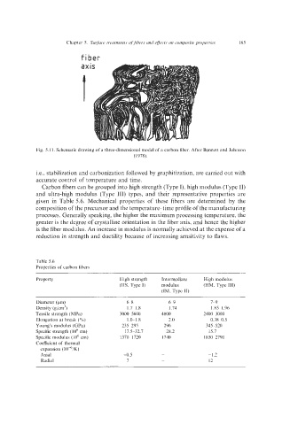
fiber
Fig. 5.1 1. Schematic drawing of a three-dimensional model of a carbon fiber. After Bennett and Johnson
(1 978).
i.e., stabilization and carbonization followed by graphitization, are carried out with
accurate control of temperature and time.
Carbon fibers can be grouped into high strength (Type I), high modulus (Type 11)
and ultra-high modulus (Type 111) types, and their representative properties are
given in Table 5.6. Mechanical properties of these fibers are determined by the
composition of the precursor and the temperature-time profile of the manufacturing
processes. Generally speaking, the higher the maximum processing temperature, the
greater is the degree of crystalline orientation in the fiber axis, and hence the higher
is the fiber modulus. An increase in modulus is normally achieved at the expense of a
reduction in strength and ductility because of increasing sensitivity to flaws.
Table 5.6
Properties of carbon fibers
Property High strength Intermediate High modulus
(HS, Type 1) modulus (HM, Type 111)
(IM, Type 11)
Diameter (Fm) 6-8 6-9 7-9
Density (gicm') 1.7-1.8 1.74 1.85-1.96
Tensile strength (MPd) 3000-5600 4800 2400-3000
Elongation at break (%) 1.0-1.8 2.0 0.38-0.5
Young's modulus (GPa) 235-295 296 345-520
Specific strength (10' cm) 17.5-32.7 28.2 15.7
Specific modulus (IO6 cm) 1370-1720 1740 1850-2790
Coefficient of thermal
expansion (lO-'/K)
Axial -0.5 -1.2
Radial 7 12