
Page 27 - Engineered Interfaces in Fiber Reinforced Composites
P. 27
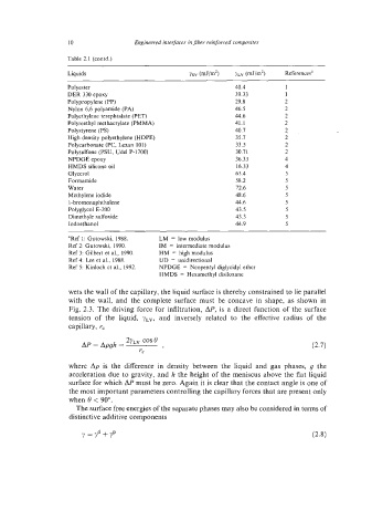
10                Engineered interfaces in fiber reinforced  composites

                    Table 2.1 (contd.)
                    Liquids                          YSV (mJ/m2)   YLV @Jim2)   Referencesa
                    Polyester                                     40.4          1
                    DER 330 epoxy                                 39.33         1
                    Polypropylene (PP)                            29.8         2
                    Nylon 6,6 polyamide (PA)                      46.5         2
                    Polyethylene terephtalate (PET)               44.6         2
                    Polymethyl methacrylate (PMMA)                41.1         2
                    Polystyrene (PS)                              40.7         -2   ~   ..-
                    High density polyethylene (HDPE)              35.7          2
                    Polycarbonate (PC, Lexan 101)                 33.5          2
                    Polysulfone (PSU, Udel P-1700)                30.71         2
                    NPDGE epoxy                                   36.33         4
                    HMDS silicone oil                             16.33         4
                    Glycerol                                      63.4          5
                    Formamide                                     58.2          5
                    Water                                         72.6          5
                    Methylene iodide                              48.6          5
                    1 -bromonaphthalene                           44.6          5
                    Polyglyd E-200                                43.5          5
                    Dimethyle sulfoxide                           43.3          5
                    Iodoethanol                                   44.9          5
                    "Ref 1: Gutowski,  1988.   LM  = low modulus
                    Ref 2: Gutowski,  1990.   IM  = intermediate modulus
                    Ref 3: Gilbert et al., 1990.   HM  = high modulus
                    Ref 4: Lee et al.,  1988.   UD  = unidirectional
                    Ref 5: Kinloch et a]., 1992.   NPDGE  = Neopentyl diglycidyl ether
                                             HMDS  = Hexamethyl disiloxane

                    wets the wall of the capillary, the liquid surface is thereby constrained to lie parallel
                    with  the  wall,  and  the  complete  surface  must  be  concave  in  shape,  as  shown  in
                    Fig. 2.3.  The driving  force for infiltration, AP, is  a direct  function of  the  surface
                    tension  of  the  liquid,  yLv,  and  inversely  related  to  the  effective  radius  of  the
                    capillary, r,
                                    2yLV COS e
                        AP = Apgh =           7
                                       rC
                    where  Ap is  the  difference in  density  between  the  liquid  and  gas  phases,  g  the
                    acceleration due to gravity, and h the height of the meniscus above the flat liquid
                    surface for which AP must be zero. Again it is clear that the contact angle is one of
                    the most important parameters controlling the capillary forces that are present only
                    when 9 < 90".
                      The surface free energies of the separate phases may also be considered in terms of
                    distinctive additive components

                        y  = yd + YP