
Page 289 - Engineered Interfaces in Fiber Reinforced Composites
P. 289
270 Engineered interfaces in jiber reinforced composites
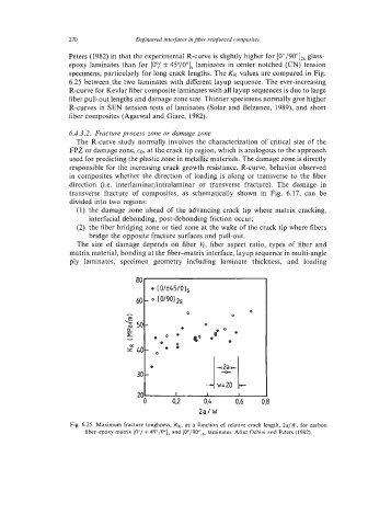
Peters (1982) in that the experimental R-curve is slightly higher for [0"/90"],, glass-
epoxy laminates than for [Oo/ f 45"/0"], laminates in center notched (CN) tension
specimens, particularly for long crack lengths. The KR values are compared in Fig.
6.25 between the two laminates with different layup sequence. The ever-increasing
R-curve for Kevlar fiber composite laminates with all layup sequences is due to large
fiber pull-out lengths and damage zone size. Thinner specimens normally give higher
R-curves in SEN tension tests of laminates (Solar and Belzunce, 1989), and short
fiber composites (Aganval and Giare, 1982).
6.4.3.2. Fracture process zone or damage zone
The R-curve study normally involves the characterization of critical size of the
FPZ or damage zone, CO, at the crack tip region, which is analogous to the approach
used for predicting the plastic zone in metallic materials. The damage zone is directly
responsible for the increasing crack growth resistance, R-curve, behavior observed
in composites whether the direction of loading is along or transverse to the fiber
direction (i.e. interlaminar/intralaminar or transverse fracture). The damage in
transverse fracture of composites, as schematically shown in Fig. 6.17, can be
divided into two regions:
(1) the damage zone ahead of the advancing crack tip where matrix cracking,
interfacial debonding, post-debonding friction occur;
(2) the fiber bridging zone or tied zone at the wake of the crack tip where fibers
bridge the opposite fracture surfaces and pull-out.
The size of damage depends on fiber 6, fiber aspect ratio, types of fiber and
matrix material, bonding at the fiber-matrix interface, layup sequence in multi-angle
ply laminates, specimen geometry including laminate thickness, and loading
3
Fig. 6.25. Maximum fracture toughness, KR, as a function of relative crack length, 2a/W, for carbon
fiber-epoxy matrix [O"/ * 45"/O"], and [0"/90"],, laminates. After Ochiai and Peters (1982).