
Page 284 - Engineered Interfaces in Fiber Reinforced Composites
P. 284
Chapter 6. Interface mechanics and fracture toughness theories 265
It is noted that these parameters become unity for an isotropic material. The two
elastic parameters, a and j , are also modified accordingly, taking into account the
anisotropy:
Y2 - Yl
E=- (6.30)
Y?+YI >
where
(6.32)
(6.33)
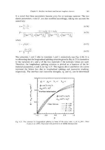
The subscripts 1 and 2 refer to materials 1 and 2, respectively (see Fig. 6.18). It is
worth noting that the longitudinal splitting criterion given by Eq. (6.27) is insensitive
to the variation of 1 and p of the two materials if the isotropic values are used.
Therefore, the longitudinal splitting criterion is plotted as a function of the bi-
material parameters, tl and p, in Fig. 6.21. The regions above and below the curves
represent the failure loci due to longitudinal splitting and transverse cracking,
respectively. The interface and transverse strengths, 0: and c;, can be determined
0.6
-
c
-
0
0
a,
x 0.4
- Interface delamin
b"
\
-
0
0
ZI
b"
0.2
I,
-8
0.0
-1.0 -0.5 0.0 0.5 1.0
a
Fig. 6.21. The criterion for longitudinal splitting in terms of the stress ratio, u,(0°/u,(90"). After
Gupta et al. (1991). Reprinted with perniission of ASME International.