
Page 283 - Engineered Interfaces in Fiber Reinforced Composites
P. 283
?21 ;;=: /
264 Engineered interfaces in $ber reinforced composites
I \ C3 * k1= 0.2
I-
-I
x h1= 2.0
/- /I
-I 4.8 0.6 0.4 0.2 0 0.2 0.4 0.6 0.8 I
a
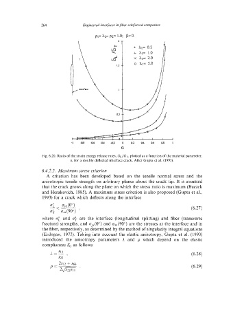
Fig. 6.20. Ratio of the strain energy release rates, GL/GT, plotted as a function of the material parameter,
a, for a doubly deflected interface crack. After Gupta et at. (1993).
6.4.2.2. Maximum stress criterion
A criterion has been developed based on the tensile normal stress and the
anisotropic tensile strength on arbitrary planes about the crack tip. It is assumed
that the crack grows along the plane on which the stress ratio is maximum (Buczck
and Herakovich, 1985). A maximum stress criterion is also proposed (Gupta et al.,
1993) for a crack which deflects along the interface
(6.27)
where 0; and 0; are the interface (longitudinal splitting) and fiber (transverse
fracture) strengths, and ~~(0') and oU(9O0) are the stresses at the interface and in
the fiber, respectively, as determined by the method of singularity integral equations
(Erdogan, 1972). Taking into account the elastic anisotropy, Gupta et al. (1993)
introduced the anisotropy parameters 1 and p which depend on the elastic
compliances Sij as follows:
(6.28)
(6.29)