
Page 278 - Engineered Interfaces in Fiber Reinforced Composites
P. 278
Chapter 6. Interface mechanics andfracture toughness theories 259
The constants kl and k2 are given by:
(6.20)
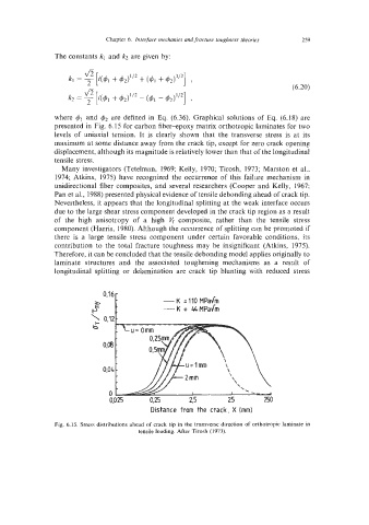
where 41 and $2 are defined in Eq. (6.36). Graphical solutions of Eq. (6.18) are
presented in Fig. 6.15 for carbon fiber-epoxy matrix orthotropic laminates for two
levels of uniaxial tension. It is clearly shown that the transverse stress is at its
maximum at some distance away from the crack tip, except for zero crack opening
displacement, although its magnitude is relatively lower than that of the longitudinal
tensile stress.
Many investigators (Tetelman, 1969; Kelly, 1970; Tirosh, 1973; Marston et al.,
1974; Atkins, 1975) have recognized the occurrence of this failure mechanism in
unidirectional fiber composites, and several researchers (Cooper and Kelly, 1967;
Pan et al., 1988) presented physical evidence of tensile debonding ahead of crack tip.
Nevertheless, it appears that the longitudinal splitting at the weak interface occurs
due to the large shear stress component developed in the crack tip region as a result
of the high anisotropy of a high vf composite, rather than the tensile stress
component (Harris, 1980). Although the occurrence of splitting can be promoted if
there is a large tensile stress component under certain favorable conditions, its
contribution to the total fracture toughness may be insignificant (Atkins, 1975).
Therefore, it can be concluded that the tensile debonding model applies originally to
laminate structures and the associated toughening mechanisms as a result of
longitudinal splitting or delamination are crack tip blunting with reduced stress
0,16
K
A
PE - =I10 MPadm
---K = 44MPadm
‘= 0.12
b
0,04
0
0,025 0,25 25 250
Distance from the crack, X (mm)
Fig. 6.15. Stress distributions ahead of crack tip in the transverse direction of orthotropic laminate in
tensile loading. After Tirosh (1973).