
Page 286 - Engineered Interfaces in Fiber Reinforced Composites
P. 286
Chapter 6. Interface mechanics and fracture toughness theories 267
KI = nnJa is the stress intensity factor, and F, the material constant, both of which
depend on the degree of anisotropy of the composite controlled by the composite
elastic moduli in the longitudinal and transverse directions, EL and ET, in-plane
Poisson ratio, VLT, and GLT. For a perfectly isotropic material,
F M n/8( 1 + vLT) FZ 0.3. Also, the material parameters, 6, and 42, are given by:
(6.36)
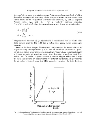
The predictions based on Eq. (6.35) are found to be consistent with the results from
finite element analysis, Fig. 6.22, for a carbon fiber-epoxy matrix orthotropic
laminate.
Based on the above analysis, Newaz (1985, 1986) measured the interfacial fracture
toughness using SEN specimens: J, = 3.7 and 6.6 kJ/m2 for unidirectional glass-
polyester and glass-epoxy composites, respectively. Clearly, these values are thought
to be over one order of magnitude greater than those determined from single fiber
pull-out tests for similar composite systems (Chua and Piggott, 1985), even though
the shear yield stresses are similar in the two different experiments. It appears that
the Jc values obtained using the SEN geometry represent the total fracture
f
m
c
(u
d
Y
U
E
u
%
r
t
m
c
(u
d
.-
c
A
n
v)
Displacement / half specimen
length
Fig. 6.22. Comparisons of the longitudinal splitting length, L,, between analysis and finite element method
for graphite fiber-epoxy matrix orthotropic laminates. After Tirosh (1973).