
Page 316 - Engineered Interfaces in Fiber Reinforced Composites
P. 316
Chapter I. Improvement of transverse fracture toughness with interface control 291
variation functions were also considered to represent the Young’s modulus and the
CTE of the interphase (Jayaraman and Reifsnider, 1993).
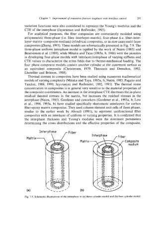
For analytical purposes, the fiber composites are conveniently modeled using
axisymmetric three-phase (i.e. fiber-interlayer-matrix), four-phase (i.e. fiber-inter-
layer-matrix-composite medium) cylindrical composites, or in rare cases multi-layer
composites (Zhang, 1993). These models are schematically presented in Fig. 7.9. The
three-phase uniform interphase model is typified by the work of Nairn (1985) and
Beneveniste et al. (1989), while Mitaka and Taya (1985a, b, 1986) were the pioneers
in developing four-phase models with interlayer/interphase of varying stiffness and
CTE values to characterize the stress fields due to thermo-mechanical loading. The
four phase composite models contain another cylinder at the outermost surface as
an equivalent composite (Christensen, 1979; Theocaris and Demakos, 1992;
Lhotellier and Brinson, 1988).
Thermal stresses in composites have been studied using numerous mathematical
models of varying complexity (Mitaka and Taya, 1985a, b; Nairn, 1985; Pagano and
Tandon, 1988, 1990; Jayaraman and Reifsnider, 1992, 1993). The thermal stress
concentration in composites is in general very sensitive to the material properties of
the composite constituents. An increase in the interphase CTE decreases the in-plane
residual thermal stresses in the matrix, but increases the residual stresses in the
interphase (Nairn, 1985). Gardener and coworkers (Gardener et al., 1993a, b; Low
et al., 1994, 1995a, b) have studied specifically elastomeric interlayers for carbon
fiber-epoxy matrix composites. They used column element unit cells of three phases,
similar to the earlier work by Aboudi (1991), to represent unidirectional fiber
composites with an interlayer of uniform or varying properties. It is confirmed that
the interphase thickness and Young’s modulus were the dominant parameters
determining the stress distributions and the effective properties of the composite,
Interphase Fi ber
medium
Fig. 7.9. Schematic illustrations of the interphase in (a) three cylinder model and (b) four cylinder model.