
Page 320 - Engineered Interfaces in Fiber Reinforced Composites
P. 320
Chapter 7. Improvement of transverse fracture toughness with interface control 30 1
u) fiber-matrix (without coating)
u)
0.4
CI
rn
8 0.3
r
rn
g 0.2
.t"
2 0.1
-
C
0-l I
0 1 2 3 4
Normalized axial distance, z/a
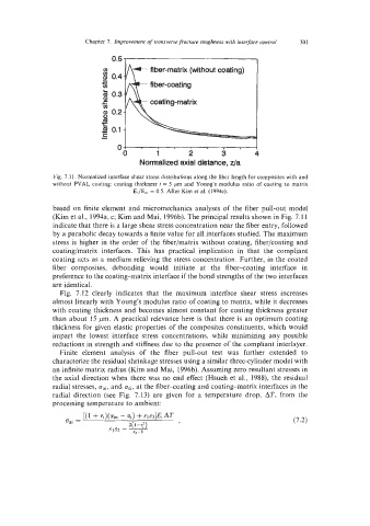
Fig. 7.1 I. Normalized interface shear stress distributions along the fiber length for composites with and
without PVAL coating: coating thickness t = 5 pm and Young's modulus ratio of coating to matrix
Ei/Em = 0.5. After Kim et al. (1994~).
based on finite element and micromechanics analyses of the fiber pull-out model
(Kim et al., 1994a, c; Kim and Mai, I996b). The principal results shown in Fig. 7.1 1
indicate that there is a large shear stress concentration near the fiber entry, followed
by a parabolic decay towards a finite value for all interfaces studied. The maximum
stress is higher in the order of the fiber/matrix without coating, fiber/coating and
coating/matrix interfaces. This has practical implication in that the compliant
coating acts as a medium relieving the stress concentration. Further, in the coated
fiber composites, debonding would initiate at the fiber-coating interface in
preference to the coating-matrix interface if the bond strengths of the two interfaces
are identical.
Fig. 7.12 clearly indicates that the maximum interface shear stress increases
almost linearly with Young's modulus ratio of coating to matrix, while it decreases
with coating thickness and becomes almost constant for coating thickness greater
than about 15 pm. A practical relevance here is that there is an optimum coating
thickness for given elastic properties of the composites constituents, which would
impart the lowest interface stress concentrations, while minimizing any possible
reductions in strength and stiffness due to the presence of the compliant interlayer.
Finite element analysis of the fiber pull-out test was further extended to
characterize the residual shrinkage stresses using a similar three-cylinder model with
an infinite matrix radius (Kim and Mai, 1996b). Assuming zero resultant stresses in
the axial direction when there was no end effect (Hsueh et al., 1988), the residual
radial stresses, cai, and oci, at the fiber-coating and coating-matrix interfaces in the
radial direction (see Fig. 7.13) are given for a temperature drop, AT, from the
processing temperature to ambient: