
Page 228 - Engineering Digital Design
P. 228
5.2 XOR-TYPE PATTERNS 199
\BC I
A\_ oo 01 ' 11 10
C
(a)
A\ 00 01 ' 11 10
(c)
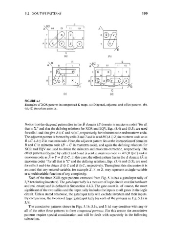
FIGURE 5.1
Examples of XOR patterns in compressed K-maps. (a) Diagonal, adjacent, and offset patterns, (b),
(c), (d) Associate patterns.
Notice that the diagonal pattern lies in the B domain (B domain in maxterm code) "for all
that is X," and that the defining relations for XOR and EQV, Eqs. (3.4) and (3.5), are used
for cells 1 and 4 to give A®C and A O C, respectively, for minterm code and maxterm code.
The adjacent pattern is formed by cells 3 and 7 and is read BC( A O Z) in minterm code or as
fi+C+AOZin maxterm code. Here, the adj acent pattern lies at the intersection of domains
B and C in minterm code (B + C in maxterm code), and again the defining relations for
XOR and EQV are used to obtain the minterm and maxterm extraction, respectively. The
offset pattern is formed by cells 5 and 6 and is read in minterm code as AY(B © C) and in
maxterm code asA + 7 + 5OC.In this case, the offset pattern lies in the A domain (A in
maxterm code) "for all that is Y," and the defining relations, Eqs. (3.4) and (3.5), are used
for cells 5 and 6 to obtain B © C and B O C, respectively. Throughout this discussion it is
assumed that any entered variable, for example X, Y, or Z, may represent a single variable
or a multivariable function of any complexity.
Each of the three XOR-type patterns extracted from Fig. 5. la has a gate/input tally of
2/5 (excluding inverters). The gate/input tally is a measure of logic circuit cost (in hardware
and real estate) and is defined in Subsection 4.4.3. The gate count is, of course, the more
significant of the two tallies and the input tally includes the inputs to all gates in the logic
circuit. Unless stated otherwise, the gate/input tally will exclude inverters and their inputs.
By comparison, the two-level logic gate/input tally for each of the patterns in Fig. 5. la is
3/8.
The associative patterns shown in Figs. 5.1b, 5.1c, and 5.Id may combine with any or
all of the other three patterns to form compound patterns. For this reason the associative
patterns require special consideration and will be dealt with separately in the following
subsection.