
Page 261 - Engineering Digital Design
P. 261
232 CHAPTER 5 / FUNCTION MINIMIZATION
\BC \BC
A\ oo 01 11 10 A\oooii i 10
0 X 0 X+Y
Y+Z Z 0 0 Y+Z X+Y
y
/ \n -ft. o
/ l
(b) (c)
\BC \BC 01 11 10
A\ 00 01 11 10 AX °°
X©Y 0
X©Y
"A
(d) (e) (f)
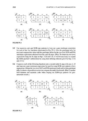
FIGURE P5.1
5.5 Use maxterm code and XOR-type patterns to loop out a gate-minimum expression
for each of the five functions represented in Fig. P5.2. Give the gate/input tally for
each and compare that value with the gate/input tallies for the two-level SOP and POS
minimum expressions obtained from the same K-maps. [Hint: To obtain the two-level
expressions from the K-maps in Figs. 5.2d and 5.2e, it will be necessary to expand
the XOR and EQV subfunctions by using their defining relations given by Eqs. (3.4)
and (3.5).]
5.6 Compress each of the following functions into a second-order K-map with axes A, B
and loop out a gate-minimum expression for each by using XOR-type patterns where
appropriate. Obtain the two-level SOP and POS minimum result and use the gate/input
tally (exclusive of possible inverters) to compare the multi-level result. (Hint: Consider
both minterm and maxterm codes when looping out XOR-type patterns for gate-
minimum results.)
\BC \BC
0 1 A\ 0° 01 1 1 10 A\ 00 01 11 10
XY 0 0 D 0 D-E E 0 0 1 X 0
X+Y $ 1 1 0 E E 1 1 XY 0 X-Y
/ f 1 / f 2 /
(a) (b) (c)
\B \BC
A\ o 1 A\ oo 01 11 10
0 C-D 0 0 0 X xeY Y
1 C©D D 1 0 X Y
^
)
/f 4 *6
(d) (e)
FIGURE P5.2