
Page 263 - Engineering Digital Design
P. 263
234 CHAPTER 5 / FUNCTION MINIMIZATION
00 01 11 10
0 0 X0Y Y 0
1 X XY 1
*
(b)
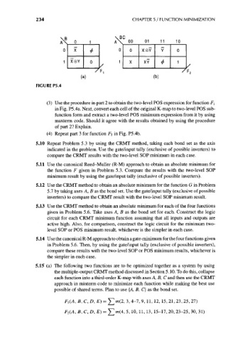
FIGURE P5.4
(3) Use the procedure in part 2 to obtain the two-level POS expression for function F\
in Fig. P5.4a. Next, convert each cell of the original K-map to two-level POS sub-
function form and extract a two-level POS minimum expression from it by using
maxterm code. Should it agree with the results obtained by using the procedure
of part 2? Explain.
(4) Repeat part 3 for function F 2 in Fig. P5.4b.
5.10 Repeat Problem 5.3 by using the CRMT method, taking each bond set as the axis
indicated in the problem. Use the gate/input tally (exclusive of possible inverters) to
compare the CRMT results with the two-level SOP minimum in each case.
5.11 Use the canonical Reed-Muller (R-M) approach to obtain an absolute minimum for
the function F given in Problem 5.3. Compare the results with the two-level SOP
minimum result by using the gate/input tally (exclusive of possible inverters).
5.12 Use the CRMT method to obtain an absolute minimum for the function G in Problem
5.7 by taking axes A, B as the bond set. Use the gate/input tally (exclusive of possible
inverters) to compare the CRMT result with the two-level SOP minimum result.
5.13 Use the CRMT method to obtain an absolute minimum for each of the four functions
given in Problem 5.6. Take axes A, B as the bond set for each. Construct the logic
circuit for each CRMT minimum function assuming that all inputs and outputs are
active high. Also, for comparison, construct the logic circuit for the minimum two-
level SOP or POS minimum result, whichever is the simpler in each case.
5.14 Use the canonical R-M approach to obtain a gate-minimum for the four functions given
in Problem 5.6. Then, by using the gate/input tally (exclusive of possible inverters),
compare these results with the two-level SOP or POS minimum results, whichever is
the simpler in each case.
5.15 (a) The following two functions are to be optimized together as a system by using
the multiple-output CRMT method discussed in Section 5.10. To do this, collapse
each function into a third-order K-map with axes A, B, C and then use the CRMT
approach in minterm code to minimize each function while making the best use
possible of shared terms. Plan to use {A, B, C} as the bond set.
Fj(A, B, C, D, E) = m(2, 3, 4-1, 9, 11, 12, 15, 21, 23, 25, 21)
F 2(A, fi, C, D, £) = £]m(4, 5, 10, 11, 13, 15-17, 20, 23-25, 30, 31)