
Page 110 - Engineering Electromagnetics, 8th Edition
P. 110
92 ENGINEERING ELECTROMAGNETICS
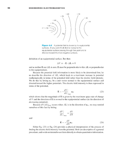
Figure 4.6 A potential field is shown by its equipotential
surfaces. At any point the E field is normal to the
equipotential surface passing through that point and is
directed toward the more negative surfaces.
definition of an equipotential surface. But then
V =−E · L = 0
and as neither E nor L is zero, E must be perpendicular to this L or perpendicular
to the equipotentials.
Because the potential field information is more likely to be determined first, let
us describe the direction of L, which leads to a maximum increase in potential
mathematically in terms of the potential field rather than the electric field intensity.
We do this by letting a N be a unit vector normal to the equipotential surface and
directed toward the higher potentials. The electric field intensity is then expressed in
terms of the potential,
dV
E =−
a N (23)
dL
max
which shows that the magnitude of E is given by the maximum space rate of change
of V and the direction of E is normal to the equipotential surface (in the direction of
decreasing potential).
Because dV/dL| max occurs when L is in the direction of a N ,we may remind
ourselves of this fact by letting
dV
dV
=
dL
max dN
and
dV
E =− a N (24)
dN
Either Eq. (23) or Eq. (24) provides a physical interpretation of the process of
finding the electric field intensity from the potential. Both are descriptive of a general
procedure,andwedonotintendtousethemdirectlytoobtainquantitativeinformation.