
Page 320 - Engineering Electromagnetics, 8th Edition
P. 320
302 ENGINEERING ELECTROMAGNETICS
this condition would lead to a measurable phase difference between each end of the
device in question.
In this chapter, we investigate wave phenomena in transmission lines. Our
objectives include (1) to understand how to treat transmission lines as circuit elements
possessing complex impedances that are functions of line length and frequency, (2) to
understand wave propagation on lines, including cases in which losses may occur,
(3) to learn methods of combining different transmission lines to accomplish a desired
objective, and (4) to understand transient phenomena on lines. ■
10.1 PHYSICAL DESCRIPTION OF
TRANSMISSION LINE PROPAGATION
To obtain a feel for the manner in which waves propagate on transmission lines,
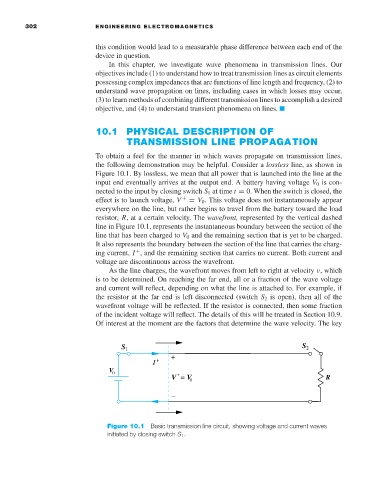
the following demonstration may be helpful. Consider a lossless line, as shown in
Figure 10.1. By lossless, we mean that all power that is launched into the line at the
input end eventually arrives at the output end. A battery having voltage V 0 is con-
nected to the input by closing switch S 1 at time t = 0. When the switch is closed, the
effect is to launch voltage, V + = V 0 . This voltage does not instantaneously appear
everywhere on the line, but rather begins to travel from the battery toward the load
resistor, R,ata certain velocity. The wavefront, represented by the vertical dashed
line in Figure 10.1, represents the instantaneous boundary between the section of the
line that has been charged to V 0 and the remaining section that is yet to be charged.
It also represents the boundary between the section of the line that carries the charg-
ing current, I , and the remaining section that carries no current. Both current and
+
voltage are discontinuous across the wavefront.
As the line charges, the wavefront moves from left to right at velocity ν, which
is to be determined. On reaching the far end, all or a fraction of the wave voltage
and current will reflect, depending on what the line is attached to. For example, if
the resistor at the far end is left disconnected (switch S 2 is open), then all of the
wavefront voltage will be reflected. If the resistor is connected, then some fraction
of the incident voltage will reflect. The details of this will be treated in Section 10.9.
Of interest at the moment are the factors that determine the wave velocity. The key
S 1 S 2
+
I +
V
0 +
V = V 0 R
_
Figure 10.1 Basic transmission line circuit, showing voltage and current waves
initiated by closing switch S 1 .