Page 346 - Engineering Electromagnetics, 8th Edition
P. 346

328                ENGINEERING ELECTROMAGNETICS

                           g                                                           g


                              in  in                                  L                      in     in

                               z = −l                        z = 0

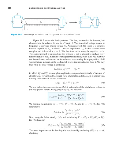
                     Figure 10.7 Finite-length transmission line configuration and its equivalent circuit.

                                        Figure 10.7 shows the basic problem. The line, assumed to be lossless, has
                                     characteristic impedance Z 0 and is of length l. The sinusoidal voltage source at
                                     frequency ω provides phasor voltage V s . Associated with the souce is a complex
                                     internal impedance, Z g ,as shown. The load impedance, Z L ,is also assumed to be
                                     complex and is located at z = 0. The line thus exists along the negative z axis.
                                     The easiest method of approaching the problem is not to attempt to analyze every
                                     reflection individually, but rather to recognize that in steady state, there will exist one
                                     net forward wave and one net backward wave, representing the superposition of all
                                     waves that are incident on the load and all waves that are reflected from it. We may
                                     thus write the total voltage in the line as
                                                                    + − jβz
                                                                              − jβz
                                                           V sT (z) = V e  + V e                     (93)
                                                                    0
                                                                             0
                                     in which V 0 +  and V 0 −  are complex amplitudes, composed respectively of the sum of
                                     all individual forward and backward wave amplitudes and phases. In a similar way,
                                     we may write the total current in the line:
                                                                    + − jβz
                                                                             − jβz
                                                            I sT (z) = I e  + I e                    (94)
                                                                             0
                                                                    0
                                     We now define the wave impedance, Z w (z), as the ratio of the total phasor voltage to
                                     the total phasor current. Using (93) and (94), this becomes:
                                                                                  − jβz
                                                              V sT (z)  V e   + V e
                                                                        + − jβz
                                                       Z w (z) ≡    =   0        0                   (95)
                                                                        + − jβz
                                                                                 − jβz
                                                               I sT (z)  I e  + I e
                                                                        0
                                                                                 0
                                     We next use the relations V 0 −  =  V , I 0 +  = V /Z 0 , and I 0 −  =−V /Z 0 . Eq. (95)
                                                                           +
                                                                  +
                                                                                            −
                                                                                            0
                                                                  0
                                                                           0
                                     simplifies to
                                                                      e   +  e
                                                                       − jβz   jβz
                                                           Z w (z) = Z 0                             (96)
                                                                      e − jβz  −  e  jβz
                                     Now, using the Euler identity, (32), and substituting   = (Z L − Z 0 )/(Z L + Z 0 ),
                                     Eq. (96) becomes
                                                                 Z L cos(βz) − jZ 0 sin(βz)

                                                      Z w (z) = Z 0                                  (97)
                                                                 Z 0 cos(βz) − jZ L sin(βz)
                                     The wave impedance at the line input is now found by evaluating (97) at z =−l,
                                     obtaining
   341   342   343   344   345   346   347   348   349   350   351