
Page 348 - Engineering Electromagnetics, 8th Edition
P. 348
330 ENGINEERING ELECTROMAGNETICS
if Z 02 is chosen so that
Z 02 = Z 01 Z 03 (103)
This technique is called quarter-wave matching and again is limited to the frequency
.
(or narrow band of frequencies) such that l = (2m + 1)λ/4. We will encounter more
examples of these techniques when we explore electromagnetic wave reflection in
Chapter 12. Meanwhile, further examples that involve the use of the input impedance
and the VSWR are presented in Section 10.12.
10.12 SOME TRANSMISSION LINE
EXAMPLES
In this section, we apply many of the results that we obtained in the previous sections
to several typical transmission line problems. We simplify our work by restricting our
attention to the lossless line.
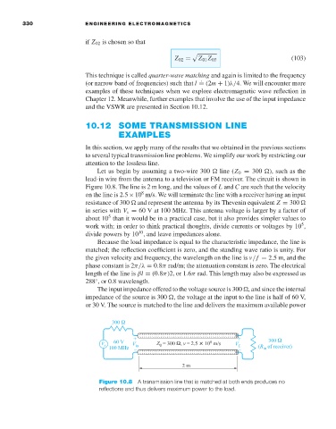
Let us begin by assuming a two-wire 300 line (Z 0 = 300 ), such as the
lead-in wire from the antenna to a television or FM receiver. The circuit is shown in
Figure 10.8. The line is 2 m long, and the values of L and C are such that the velocity
8
on the line is 2.5×10 m/s. We will terminate the line with a receiver having an input
resistance of 300 and represent the antenna by its Thevenin equivalent Z = 300
in series with V s = 60 V at 100 MHz. This antenna voltage is larger by a factor of
5
about 10 than it would be in a practical case, but it also provides simpler values to
5
work with; in order to think practical thoughts, divide currents or voltages by 10 ,
10
divide powers by 10 , and leave impedances alone.
Because the load impedance is equal to the characteristic impedance, the line is
matched; the reflection coefficient is zero, and the standing wave ratio is unity. For
the given velocity and frequency, the wavelength on the line is v/f = 2.5m, and the
phase constant is 2π/λ = 0.8π rad/m; the attenuation constant is zero. The electrical
length of the line is βl = (0.8π)2, or 1.6π rad. This length may also be expressed as
288 ,or 0.8 wavelength.
◦
The input impedance offered to the voltage source is 300 , and since the internal
impedance of the source is 300 , the voltage at the input to the line is half of 60 V,
or 30 V. The source is matched to the line and delivers the maximum available power
Figure 10.8 A transmission line that is matched at both ends produces no
reflections and thus delivers maximum power to the load.