
Page 413 - Engineering Electromagnetics, 8th Edition
P. 413
CHAPTER 11 The Uniform Plane Wave 395
may change, however, as functions of time and position, depending on how the wave
was generated or on what type of medium it is propagating through. Thus a complete
description of an electromagnetic wave would not only include parameters such as
its wavelength, phase velocity, and power, but also a statement of the instantaneous
orientation of its field vectors. We define the wave polarization as the time-dependent
electric field vector orientation at a fixed point in space. A more complete character-
ization of a wave’s polarization would in fact include specifying the field orientation
at all points because some waves demonstrate spatial variations in their polarization.
Specifying only the electric field direction is sufficient, since magnetic field is readily
found from E using Maxwell’s equations.
In the waves we have previously studied, E wasina fixed straight orientation for
all times and positions. Such a wave is said to be linearly polarized.Wehave taken E
to lie along the x axis, but the field could be oriented in any fixed direction in the xy
plane and be linearly polarized. For positive z propagation, the wave would in general
have its electric field phasor expressed as
e
E s = (E x0 a x + E y0 a y )e −αz − jβz (91)
where E x0 and E y0 are constant amplitudes along x and y. The magnetic field is readily
found by determining its x and y components directly from those of E s . Specifically,
H s for the wave of Eq. (91) is
E y0 E x0
e
H s = [H x0 a x + H y0 a y ] e −αz e − jβz = − a x + a y e −αz − jβz (92)
η η
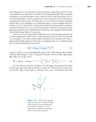
The two fields are sketched in Figure 11.4. The figure demonstrates the reason
for the minus sign in the term involving E y0 in Eq. (92). The direction of power flow,
given by E × H,isin the positive z direction in this case. A component of E in the
Figure 11.4 Electric and magnetic
field configuration for a general linearly
polarized plane wave propagating in
the forward z direction (out of the
page). Field components correspond
to those in Eqs. (91) and (92).