
Page 417 - Engineering Electromagnetics, 8th Edition
P. 417
CHAPTER 11 The Uniform Plane Wave 399
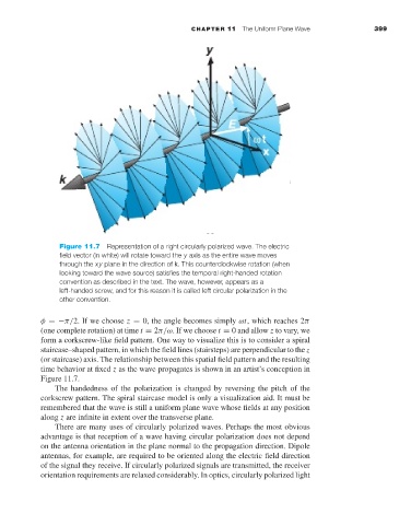
Figure 11.7 Representation of a right circularly polarized wave. The electric
field vector (in white) will rotate toward the y axis as the entire wave moves
through the xy plane in the direction of k. This counterclockwise rotation (when
looking toward the wave source) satisfies the temporal right-handed rotation
convention as described in the text. The wave, however, appears as a
left-handed screw, and for this reason it is called left circular polarization in the
other convention.
φ =−π/2. If we choose z = 0, the angle becomes simply ωt, which reaches 2π
(one complete rotation) at time t = 2π/ω.Ifwe choose t = 0 and allow z to vary, we
form a corkscrew-like field pattern. One way to visualize this is to consider a spiral
staircase–shaped pattern, in which the field lines (stairsteps) are perpendicular to the z
(or staircase) axis. The relationship between this spatial field pattern and the resulting
time behavior at fixed z as the wave propagates is shown in an artist’s conception in
Figure 11.7.
The handedness of the polarization is changed by reversing the pitch of the
corkscrew pattern. The spiral staircase model is only a visualization aid. It must be
remembered that the wave is still a uniform plane wave whose fields at any position
along z are infinite in extent over the transverse plane.
There are many uses of circularly polarized waves. Perhaps the most obvious
advantage is that reception of a wave having circular polarization does not depend
on the antenna orientation in the plane normal to the propagation direction. Dipole
antennas, for example, are required to be oriented along the electric field direction
of the signal they receive. If circularly polarized signals are transmitted, the receiver
orientation requirements are relaxed considerably. In optics, circularly polarized light