
Page 415 - Engineering Electromagnetics, 8th Edition
P. 415
CHAPTER 11 The Uniform Plane Wave 397
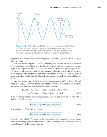
Figure 11.5 Plots of the electric field component magnitudes in Eq. (95) as
functions of z. Note that the y component lags behind the x component in z.
As time increases from zero, both waves travel to the right, as per Eq. (94).
Thus, to an observer at a fixed location, the y component leads in time.
magnitude at a distance of one wavelength in z (for fixed t)orata time t = 2π/ω
later (at a fixed z).
For illustration purposes, if we take the length of the field vector as a measure
of its magnitude, we find that at a fixed position, the tip of the vector traces out the
shape of an ellipse over time t = 2π/ω. The wave is said to be elliptically polarized.
Elliptical polarization is in fact the most general polarization state of a wave, since
it encompasses any magnitude and phase difference between E x and E y . Linear
polarization is a special case of elliptical polarization in which the phase difference
is zero.
Another special case of elliptical polarization occurs when E x0 = E y0 = E 0 and
when φ =±π/2. The wave in this case exhibits circular polarization.To see this,
we incorporate these restrictions into Eq. (94) to obtain
E(z, t) = E 0 [cos(ωt − βz)a x + cos(ωt − βz ± π/2)a y ]
= E 0 [cos(ωt − βz)a x ∓ sin(ωt − βz)a y ] (96)
If we consider a fixed position along z (such as z = 0) and allow time to vary, (96),
with φ =+π/2, becomes
E(0, t) = E 0 [cos(ωt)a x − sin(ωt)a y ] (97)
If we choose −π/2in (96), we obtain
E(0, t) = E 0 [cos(ωt)a x + sin(ωt)a y ] (98)
The field vector of Eq. (98) rotates in the counterclockwise direction in the xy plane,
while maintaining constant amplitude E 0 , and so the tip of the vector traces out a
circle. Figure 11.6 shows this behavior.