
Page 444 - Engineering Electromagnetics, 8th Edition
P. 444
426 ENGINEERING ELECTROMAGNETICS
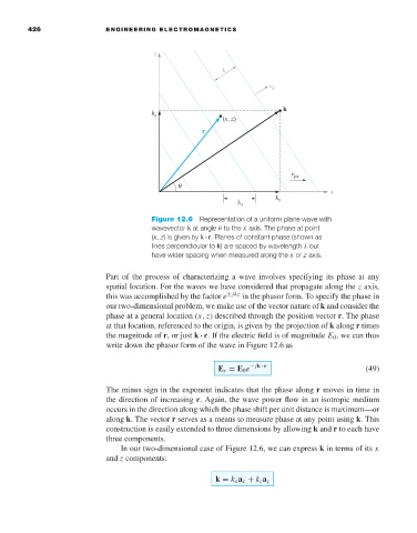
Figure 12.6 Representation of a uniform plane wave with
wavevector k at angle θ to the x axis. The phase at point
(x, z)is given by k · r. Planes of constant phase (shown as
lines perpendicular to k)are spaced by wavelength λ but
have wider spacing when measured along the x or z axis.
Part of the process of characterizing a wave involves specifying its phase at any
spatial location. For the waves we have considered that propagate along the z axis,
this was accomplished by the factor e ± jkz in the phasor form. To specify the phase in
our two-dimensional problem, we make use of the vector nature of k and consider the
phase at a general location (x, z) described through the position vector r. The phase
at that location, referenced to the origin, is given by the projection of k along r times
the magnitude of r,or just k · r.If the electric field is of magnitude E 0 ,we can thus
write down the phasor form of the wave in Figure 12.6 as
E s = E 0 e − jk · r (49)
The minus sign in the exponent indicates that the phase along r moves in time in
the direction of increasing r.Again, the wave power flow in an isotropic medium
occurs in the direction along which the phase shift per unit distance is maximum—or
along k. The vector r serves as a means to measure phase at any point using k. This
construction is easily extended to three dimensions by allowing k and r to each have
three components.
In our two-dimensional case of Figure 12.6, we can express k in terms of its x
and z components:
k = k x a x + k z a z