
Page 447 - Engineering Electromagnetics, 8th Edition
P. 447
CHAPTER 12 Plane Wave Reflection and Dispersion 429
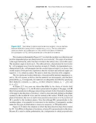
Figure 12.7 Geometries for plane wave incidence at angle θ 1 onto an interface
between dielectrics having intrinsic impedances η 1 and η 2 . The two polarization
cases are shown: (a) p-polarization (or TM), with E in the plane of incidence;
(b) s-polarization (or TE), with E perpendicular to the plane of incidence.
The situation is illustrated in Figure 12.7, in which the incident wave direction and
position-dependent phase are characterized by wavevector k . The angle of incidence
+
1
is the angle between k and a line that is normal to the surface (the x axis in this case).
+
1
The incidence angle is shown as θ 1 . The reflected wave, characterized by wavevector
k , will propagate away from the interface at angle θ . Finally, the transmitted wave,
−
1
1
characterized by k 2 , will propagate into the second region at angle θ 2 as shown. One
would suspect (from previous experience) that the incident and reflected angles are
equal (θ 1 = θ ), which is correct. We need to show this, however, to be complete.
1
The two media are lossless dielectrics, characterized by intrinsic impedances η 1
and η 2 .We will assume, as before, that the materials are nonmagnetic, and thus have
permeability µ 0 . Consequently, the materials are adequately described by specifying
√
their dielectric constants, r1 and r2 ,or their refractive indices, n 1 = r1 and
√
n 2 = r2 .
In Figure 12.7, two cases are shown that differ by the choice of electric field
orientation. In Figure 12.7a, the E field is polarized in the plane of the page, with H
therefore perpendicular to the page and pointing outward. In this illustration, the plane
of the page is also the plane of incidence, which is more precisely defined as the plane
spanned by the incident k vector and the normal to the surface. With E lying in the
plane of incidence, the wave is said to have parallel polarization or to be p-polarized
(E is parallel to the incidence plane). Note that although H is perpendicular to the
incidence plane, it lies parallel (or transverse) to the interface. Consequently, another
name for this type of polarization is transverse magnetic, or TM polarization.
Figure 12.7b shows the situation in which the field directions have been rotated
by 90 .Now H lies in the plane of incidence, whereas E is perpendicular to the plane.
◦
Because E is used to define polarization, the configuration is called perpendicular