
Page 101 - Engineering drawing from first principles using AutoCAD
P. 101
94 Engineering drawinq [rom first principles
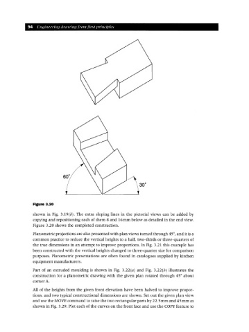
Figure 3.20
shown in Fig. 3.1 9(b). The extra sloping lines in the pictorial views can be added by
copying and repositioning each of them 8 and 16 mm below as detailed in the end view.
Figure 3.20 shows the completed construction.
Planometric projections are also presented with plan views turned through 45°, and it is a
common practice to reduce the vertical heights to a half, two-thirds or three-quarters of
the true dimensions in an attempt to improve proportions. In Fig. 3.21 this example has
been constructed with the vertical heights changed to three-quarter size for comparison
purposes. Planometric presentations are often found in catalogues supplied by kitchen
equipment manufacturers.
Part of an extruded moulding is shown in Fig. 3.22 (a) and Fig. 3.22 (b) illustrates the
construction for a planometric drawing with the given plan rotated through 45° about
corner A.
All of the heights from the given front elevation have been halved to improve propor-
tions, and two typical constructional dimensions are shown. Set out the given plan view
and use the MOVE command to raise the two rectangular parts by 22.5 mm and 45 mm as
shown in Fig. 3.29. Plot each of the curves on the front face and use the COpy feature to