
Page 106 - Engineering drawing from first principles using AutoCAD
P. 106
Chapter ~
Orthographic
projection
This chapter introduces:
• First angle or European projection.
• Third angle or American projection.
• Projection examples and the selection of views.
• Standard projection symbols.
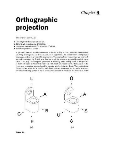
A pictorial view of a cable connector is shown in Fig. 4.1 and detailed dimensioned
drawings are required for its manufacture. Draughtsmen use a multi-view orthographic
projection system to present this information. Two methods are in common use and both
are acknowledged by British and International Standards as acceptable and of equal
merit. First angle or European projection is probably more widely used in Europe and
is normally used in Standards here for uniformity of presentation. Third angle is the
American projection method and in regular use by industry here. The professional
draughtsman needs to be familiar with both systems. Drawings are not only produced
for manufacturing purposes but also to communicate information for readers in other
u o
~
*
o o
c/ '8 U/ '8
t t
E A
.....
(a) (b)
Figure 4.1