
Page 110 - Engineering drawing from first principles using AutoCAD
P. 110
Orthographic projection 103
R15 015
o
LO
o
M
R15 020
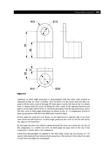
Figure 4.5
American or third angle projection is demonstrated with the other cube marked as
indicated on Fig. 4.6. Start, as before, with the letter S in the centre and note that you
need to lift the cube, rotate it through 90°then place it on the left side of the S to obtain
letter U. Repeat from the centre by lifting the cube, rotate in the opposite direction and
place it on the right side for letter A. Check the procedure with the top and bottom views.
The five views in third angle projection are drawn in Fig. 4.7. A comparison of both of
these presentations will show the differences between them.
In first angle the projected view drawn on the right-hand or opposite side of the front
view shows the left-hand face. In third angle projection the view on the left side shows
the adjacent left-hand face.
In first angle the plan view which is drawn beneath the front view shows the top face of
the component, i.e. a bird's eye view. In third angle the plan view of the top of the
component is drawn above the component.
Check how the principles are applied to the other sides. Study Fig. 4.4 and Fig. 4.7: we
started with identical front views in both projections. The position of the other two pairs
of end views and plans are exchanged.