
Page 112 - Engineering drawing from first principles using AutoCAD
P. 112
Orthographic projection 105
-
~
- - -
- - -
I I
I I I I I I
I I I I I I
I I I I
I I I I
I I I I I I
I I I
I I I
I I I I I I
I I
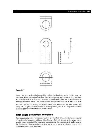
Figure 4.7
Remember you can draw in first or third angle projection but must state which one you
have used. What you cannot do is draw three views of a component where the projections
are mixed with one in first and the other in third angle, since some features can be
wrongly positioned and will not conform with design intentions. Please see a later note.
You will find that in industry the words 'views' and 'elevations' are widely used. We
freely refer to 'plans' with reference to drawings of all parts of buildings and therefore
must accept broad interpretations of these terms.
First angle projection exercises
Four isometric drawing examples were given previously in Fig. 3.3 and drawn on a grid
of equilateral triangles with IOmm sides. Figure 4.8(a)-(d) show five first angle ortho-
graphic views for each of the examples, assuming that the arrows 1, 2, 3, and 4 point to
the front views. These exercises are designed to rearrange selected parts from existing
drawings to make new drawings.