
Page 109 - Engineering drawing from first principles using AutoCAD
P. 109
102 Engineering drawinq [rom first principles
a drawing, the draughtsman must make a decision to select a suitable front view as their
job is to present the component in the clearest possible manner to convey its shape and
form to the reader. There are five possible viewing directions that are square to the faces
of the component. An addition view can be taken from the rear if required. You can look
at any other angle from space and draw auxiliary projections, but the geometrical
constructions become involved. Some examples are provided later in the text.
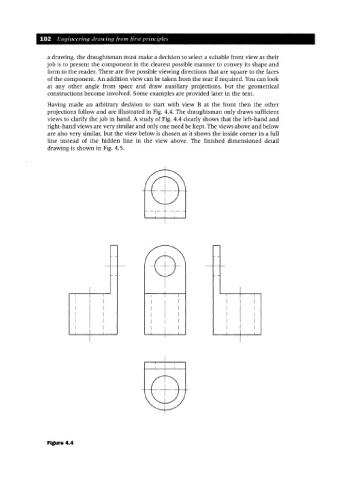
Having made an arbitrary decision to start with view B at the front then the other
projections follow and are illustrated in Fig. 4.4. The draughtsman only draws sufficient
views to clarify the job in hand. A study of Fig. 4.4 clearly shows that the left-hand and
right-hand views are very similar and only one need be kept. The views above and below
are also very similar, but the view below is chosen as it shows the inside corner in a full
line instead of the hidden line in the view above. The finished dimensioned detail
drawing is shown in Fig. 4.5.
I
I I I
I I I
I I
I I
I I
I I
I I
Figure 4.4