
Page 107 - Engineering drawing from first principles using AutoCAD
P. 107
100 Enqineerinq drawinq [rom first principles
professions. Drawings may be used as legal documents. The drawing must therefore be
clear, accurate, concise and free of any ambiguity. To assist interpretation of multi-view
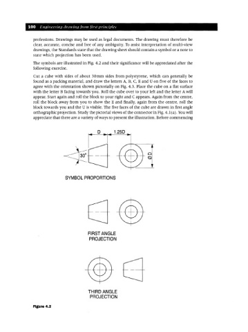
drawings, the Standards state that the drawing sheet should contain a symbol or a note to
state which projection has been used.
The symbols are illustrated in Fig. 4.2 and their significance will be appreciated after the
following exercise.
Cut a cube with sides of about 30mm sides from polystyrene, which can generally be
found as a packing material, and draw the letters A, B, C, E and U on five of the faces to
agree with the orientation shown pictorially on Fig. 4.3. Place the cube on a flat surface
with the letter B facing towards you. Roll the cube over to your left and the letter A will
appear. Start again and roll the block to your right and C appears. Again from the centre,
roll the block away from you to show the E and finally, again from the centre, roll the
block towards you and the U is visible. The five faces of the cube are drawn in first angle
orthographic projection. Study the pictorial views of the connector in Fig. 4.1 (a). Youwill
appreciate that there are a variety of ways to present the illustration. Before commencing
D 1.25D
SYMBOL PROPORTIONS
FIRST ANGLE
PROJECTION
THIRD ANGLE
PROJECTION
Figure 4.2