
Page 116 - Engineering drawing from first principles using AutoCAD
P. 116
Orthoqraphic projection 109
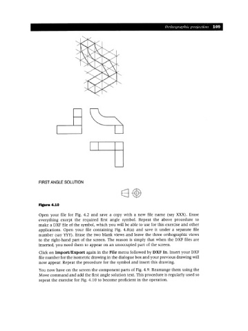
FIRST ANGLE SOLUTION
Figure 4.10
Open your file for Fig. 4.2 and save a copy with a new file name (say XXX). Erase
everything except the required first angle symbol. Repeat the above procedure to
make a DXFfile of the symbol, which you will be able to use for this exercise and other
applications. Open your file containing Fig. 4.8(a) and save it under a separate file
number (say YYY). Erase the two blank views and leave the three orthographic views
to the right-hand part of the screen. The reason is simply that when the DXF files are
inserted, you need them to appear on an unoccupied part of the screen.
Click on Import/Export again in the File menu followed by DXF In. Insert your DXF
file number for the isometric drawing in the dialogue box and your previous drawing will
now appear. Repeat the procedure for the symbol and insert this drawing.
You now have on the screen the component parts of Fig. 4.9. Rearrange them using the
Move command and add the first angle solution text. This procedure is regularly used so
repeat the exercise for Fig. 4.10 to become proficient in the operation.