
Page 120 - Engineering drawing from first principles using AutoCAD
P. 120
Text and dimensions 113
3 HOLES 010
20 15
R10
A ,....
~
LO
C\J
,....
LO
LO
co
024
co
C\J
20
66
80
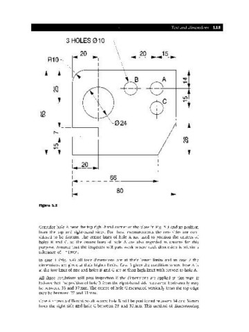
Figure 5.3
Consider hole A near the top right-hand corner of the plate in Fig. 5.3 and its position
from the top and right-hand sides. For these measurements the two sides are con-
sidered to be datums. The centre lines of hole A are used to position the centres of
holes Band C, so the centre lines of hole A are also regarded as datums for this
purpose. Assume that the inspector will pass work where each dimension is within a
tolerance of ± 1mm.
In case 1 (Fig. 5.4) all four dimensions are at their lower limits and in case 2 the
dimensions are given at their higher limits. Case 3 gives the condition where hole A is
at the low limit of size and holes Band C are at their high limit with respect to hole A.
All three conditions will pass inspection if the dimensions are applied in this way. It
follows that the position of hole B from the right-hand side measured horizontally may
be between 33 and 37mm. The centre of hole C measured vertically from the top edge
may be between 27 and 31mm.
Case 4 shows a different result where hole B will be positioned between 34 and 36mm
from the right side and hole C between 28 and 30mm. This method of dimensioning