
Page 122 - Engineering drawing from first principles using AutoCAD
P. 122
Text and d;111CnS;OllL\' 115
be inserted leaving a 1mm gap at the drawing outline and extending past the arrow tip by
1mm. Any small overruns with lines can easily be tidied up using the BREAI( feature.
Likewise, lines can easily be added accurately where necessary if the SNAP feature is
used.
Draw a single arrow 4mm long and 2mm wide using the SOLID option in the Draw menu
making sure that SNAPis engaged. Copy the arrow three times and use ROTATE three
times to obtain the four arrows as shown. I simply copy them wherever they are needed
and snap them into position. The arrows for sloping dimensions are copied into the
vicinity then oriented with the ROTATE option and positioned exactly where required
with the MOVEfeature. I personally find that to be in complete separate command of the
arrow, text, dimension and projection lines is very desirable for editing and repositioning
dimensioning details on original work.
I also find it quicker to place in a space away from the drawing a text list of numbers and
notes I require and then rotate as necessary and move them into position accurately,
taking advantage of the ZOOM feature.
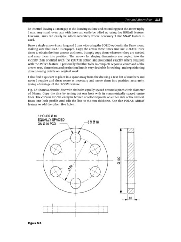
Fig. 5.5 shows a circular disc with six holes equally spaced around a pitch circle diameter
of 70mm. Copy the disc by setting out one hole with its symmetrically spaced centre
lines. The circular arc can easily be broken at selected points on either side of the vertical.
Draw one hole profile and edit the line to O.4mm thickness. Use the POLAR ARRAY
feature to add the other five holes.
6 HOLES 016
EQUALLY SPACED
ON070 PCD 6X016
o
o
Figure 5.5