
Page 124 - Engineering drawing from first principles using AutoCAD
P. 124
Text and dimensions 117
Notice in the plan view that if hidden detail is required, then the dotted lines for the holes
are oriented about the projection of the pitch circle. The end view here shows a sectional
view, assuming the disc to be cut along the vertical centre line. The three areas where
material is cut are shown cross-hatched at 45°. Twomethods of dimensioning the holes
are given.
Full instructions may be stated as shown. If spacings are self-evident then the note
'equally spaced' may be omitted. Where a number of holes of the same size are drawn
on the same view, then the short note here is acceptable. In this case the size of the pitch
circle is given separately.
Limits and fits
Many components, such as some garden tools, work in a completely satisfactory manner
after manufacture to an acceptable standard where tight dimensional controls are not
necessary. However, production to a higher degree of precision is needed for more
sophisticated assemblies where dimensional accuracy is vital for successful operation in
service.
It is taken for granted that if a component in, for example, a washing machine or a car is
broken or worn out, you will be able to replace it with a spare part. Mass production
techniques are possible because components in an assembly are interchangeable and the
designer selects suitable dimensions to ensure that an assembly functions in the intended
manner.
Since exact measurements cannot be made, the designer selects, when necessary, accep-
table high and low limits of size for each important feature dimension. If the component
is manufactured to a size somewhere between them, then it will be passed by the
inspector. Dimensions for high and low limits are each checked by 'go' and 'no go'
inspection gauges to ensure that the final product size is not too big or not too small.
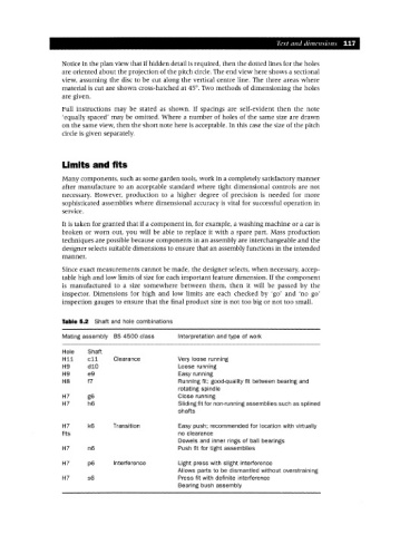
Table 5.2 Shaft and hole combinations
Mating assembly as 4500 class Interpretation and type of work
Hole Shaft
Hii cii Clearance Very loose running
H9 diD Loose running
H9 e9 Easy running
H8 f7 Running fit; good-quality fit between bearing and
rotating spindle
H7 g6 Close running
H7 h6 Sliding fit for non-running assemblies such as splined
shafts
H7 k6 Transition Easy push; recommended for location with virtually
fits no clearance
Dowels and inner rings of ball bearings
H7 n6 Push fit for tight assemblies
H7 p6 Interference Light press with slight interference
Allows parts to be dismantled without overstraining
H7 s6 Press fit with definite interference
Bearing bush assembly