
Page 119 - Engineering drawing from first principles using AutoCAD
P. 119
112 Engineering drawinq [1"0111 first principles
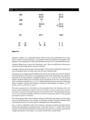
056 60.00 30.12
/ 60.04 30.00
056 0.4 0
± /
056 60±0.4 e 30.12
60 30.00
100%
15 15 5 5 3 3
32 32 16 16 4 4
Figure 5.2
diameters, widths, etc. A particular feature which is vital to the performance of a comp-
onent is called a 'functional feature'. An example could be the diameter of a spindle or the
diameter of a locating peg. The associated dimension isknown as a 'functional dimension'.
Auxiliary dimensions are given for information only. They are additional to dimensions
used in manufacturing and are shown in brackets.
A designer will use preferred sizes where possible. These can be considered to relate to the
sizes of standard tools, e.g. drills, taps, dies and raw material stocks.
Dimensions are normally stated in millimetres, but the unit symbol 'mm' may be omitted.
The drawing sheet should have a note stating the units used. Dimensions are quoted on
drawings to the least number of significant figures, e.g. 25 and not 25.0. The decimal
marker should be bold, given a full letter space and placed on the line. Dimensions less
than 1 should be preceded by 0, e.g. 0.75. Angular dimension may be quoted on drawings
either in degrees, minutes and seconds or in degrees and decimals of a degree, e.g. 25°;
25°30' or 25.5°; 25°30'30" or 25.55°.
The main components of a dimension are the projection lines, the dimension lines, the
arrows and the appropriate numbers and notes. In order to create a style of your own it is
necessary to keep to certain standard practices and repeat them. Most drawings form part
of a set, for example assemblies and their associated component details, so the general
presentation must be consistent.
All CAD programs offer various options relating to dimensioning practice and the appli-
cation of the dimensions to the drawing. At this stage, perhaps it would be helpful to take
a drawing and point out certain aspects regarding layout and positioning.
Fig. 5.3 shows a small plate with various features. The plate would be manufactured by
cutting and machining a rectangular piece of material of size 65 X 80mm. The various
features on the plate are positioned from the sides and each side would be expected to be
straight and square to the surface. All surfaces should have a good finish.