
Page 121 - Engineering drawing from first principles using AutoCAD
P. 121
114 Engineering drawinq [rom first principles
21 16
19 14
CASE 1 CASE 2
21 14
35
15
CASE 3
CASE 4
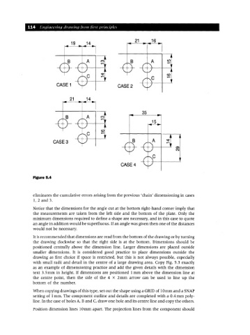
Figure 5.4
eliminates the cumulative errors arising from the previous 'chain' dimensioning in cases
1,2 and 3.
Notice that the dimensions for the angle cut at the bottom right-hand corner imply that
the measurements are taken from the left side and the bottom of the plate. Only the
minimum dimensions required to define a shape are necessary, and in this case to quote
an angle in addition would be superfluous. If an angle was given then one of the distances
would not be necessary.
It is recommended that dimensions are read from the bottom of the drawing or by turning
the drawing clockwise so that the right side is at the bottom. Dimensions should be
positioned centrally above the dimension line. Larger dimensions are placed outside
smaller dimensions. It is considered good practice to place dimensions outside the
drawing as first choice if space is restricted, but this is not always possible, especially
with small radii and detail in the centre of a large drawing area. Copy Fig. 5.3 exactly
as an example of dimensioning practice and add the given details with the dimension
text 3.5 mm in height. If dimensions are positioned 1mm above the dimension line at
the centre point, then the side of the 4 X 2mm arrow can be used to line up the
bottom of the number.
When copying drawings of this type, set out the shape using a GRIDof 10mm and a SNAP
setting of 1mm. The component outline and details are completed with a O.4mm poly-
line. In the case of holes A, Band C, draw one hole and its centre line and copy the others.
Position dimension lines IOmm apart. The projection lines from the component should