
Page 125 - Engineering drawing from first principles using AutoCAD
P. 125
118 Engineering drawinq f1"o111 first principles
Measurements are taken from clearly defined datum axes, planes or surfaces identified
on the drawing. The differences between high and low limits vary according to the size of
work and the degree of precision required. The mathematical difference between high
and low limits is called the 'tolerance'. Toleranced dimensions for very precise and
accurate work invariably increase production costs. Shape and form are controlled by
the application of limits and fits. British Standards have made recommendations for
tolerances to provide different grades of fits for various combinations of shafts and holes
and extracts are given in Table 5.1 shown later with typical examples.
Mass production methods require manufacturers to supply interchangeable parts, but
remember that if many identical components are required, we only need one drawing for
each component. Thus dimensions must be applied with care in a clear unambiguous
manner.
Table 5.2 shows the ISO recommendations for different combinations. The complete ISO
system of limits and fits gives a large number of combinations, but in practice the majority
of fits can be provided by the selection given in Table 5.2.
Note the term 'hole basis' at the head of the table. This system of fits is designed to associate
different shaft sizes with a single hole. Youwill appreciate that with a hole obtained from a
25 mm drill, for instance, it is difficult to vary its size after it has been manufactured. If a
peg of 25 mm nominal diameter is to be fitted into the hole, then for an easier fit it is more
convenient to grind a little off the male part than to increase the size of the hole.
Applications in heavy engineering often do require various diameters to fit shafts of
standard size and there is also a 'shaft basis' system available.
Clearance fits always provide a clearance which means that the shaft is always smaller
than the hole. They are often referred to as running fits. Interference fits occur where the
shaft is always of a larger diameter than the hole and pressure is required to force
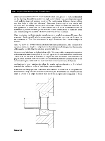
Figure 5.6