
Page 129 - Engineering drawing from first principles using AutoCAD
P. 129
122 Engineering drawinq [rom first principles
I
-
j~ ~~ I
v - 0A
~ ,r I
Jl
0 ~ 0B
N DIA SIZE
lr
~ 20.000
~l A 19.087
I
a ~ 0C 40.000
('f) B
39.084
u 80.000
C
n 79.078
0 I - - 0A
N
,r 1F
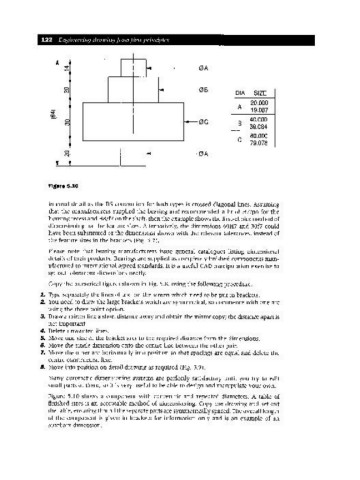
Figure 5.10
internal detail as the BS convention for both types is crossed diagonal lines. Assuming
that the manufacturers supplied the bearing and recommended a fit of H7/p6 for the
housing recess and H8/f7 on the shaft, then the example shows the first-choice method of
dimensioning for the feature sizes.·Alternatively, the dimensions 60H7 and 30f7 could
have been substituted or the dimensions shown with the relevant tolerances, instead of
the feature sizes in the brackets (Fig. 5.7).
Please note that bearing manufacturers issue general catalogues listing dimensional
details of their products. Bearings are supplied as completely finished components man-
ufactured to international agreed standards. It is a useful CAD manipulation exercise to
set out toleranced dimensions neatly.
Copy the numerical figures shown in Fig. 5.8, using the following procedure.
1. Type separately the lines of text on the screen which need to be put in brackets.
2. You need to draw the large brackets which are symmetrical, so commence with one arc
using the three-point option.
3. Draw a mirror line a short distance away and obtain the mirror copy; the distance apart is
not important.
4. Delete unwanted lines.
5. Move one side of the bracket arcs to the required distance from the dimensions.
6. Move the single dimension onto the centre line between the other pair.
7. Move the other arc horizontally into position so that spacings are equal and delete the
centre construction line.
B. Move into position on detail drawing as required (Fig. 5.9).
Many automatic dimensioning systems are perfectly satisfactory until you try to edit
small parts of them, so it is very useful to be able to design and manipulate your own.
Figure 5.10 shows a component with concentric and repeated diameters. A table of
finished sizes is an acceptable method of dimensioning. Copy the drawing and set out
the table, ensuring that all the separate parts are symmetrically spaced. The overall length
of the component is given in brackets for information only and is an example of an
auxiliary dimension.