
Page 133 - Engineering drawing from first principles using AutoCAD
P. 133
126 Engineering drawinq [rom first principles
understanding now. Complete the plan view and add the hidden detail lines and
dimensions. Erase the construction lines on your finished solution. Note that the curve
in the plan view is a semi-ellipse.
The component illustrated in Fig. 6.3 consists basically of two semicircular parts which
are cut by flat surfaces. The four curves in the plan view are semi-ellipses which can
be added after positioning the major and minor axes. Construction lines are included
to fix the necessary points BCD and EFG. Draw the ellipses and remove the unwanted
parts. Finish the outline with a O.4mm polyline and add the dimensions and section
plane.
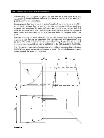
The example in Fig. 6.4 shows a tapered block with a curved surface, and it is required
to project a plan view. In the front view, four random points have been taken along
the curve. The width at each position is obtained by looking directly onto the face, and
the measurement from the end view is transferred to the plan. Dimension P is typical.
A line through the intersections from the view above will give the required curve. Use the
POLYLINE command and then the FIT option to modify the straight lines into a curve
passing through the points of intersection.
44 ~I
r
-, 1--
1& I I I \
/ T I p ~
~
1
1
I \
-------- I 1
.~ I
----- ~ <, -,
~l
<,
l"""'- <,
I
o,
--- - - -
1-
/ -, -.
" ~ "'J
--------
Figure 6.4