
Page 135 - Engineering drawing from first principles using AutoCAD
P. 135
128 Engineering drawinq [rom first principles
-+-
g ---1--- ~-.,...--_+__--.,.__~
15
LL
~
co
........
---If- --+--Z - --- -- ---~
o
o
~
---,....~_+--__ w I-----------""*""
I
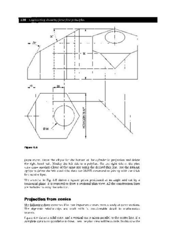
Figure 6.6
Draw menu. Draw the ellipse for the bottom of the cylinder in projection and delete
the right-hand half. Modify the left side to a polyline. On the right side of the plan
view draw another ellipse of the same size using the dashed thin line. Use the BREAI(
option to delete the left hand side, then the MOVE command to join up with the thick
line semi-ellipse.
The exercise in Fig. 6.8 shows a square prism positioned at an angle and cut by a
horizontal plane. It is required to draw a sectional plan view. All the construction lines
are included to copy the solution.
Projection from conics
The following three exercises illustrate important curves from a study of conic sections.
The algebraic relationships are dealt with in considerable detail in mathematics
courses.
Figure 6.9 shows a solid cone, and a vertical cut is taken parallel to the centre line. If a
complete cone is cut parallel to its base, then the plan view will be a circle. In this case the