
Page 134 - Engineering drawing from first principles using AutoCAD
P. 134
Three-dimensional projection exercises 127
(2J42-~
1
'''''
/ / Y V" -......... -, C\I
C')
1/ / I \
1/ - I
/ -I- I -~-1----
/ / ~ /
/ , ~ I /
/
.> ~ / "'- ~
I I
I
--
----- --- """"'-....
-
.......~
./" -. I
1/ "'" i\ ~
V ~
-f--- - - - -,
\
-, II .~
.............. ./ r-,
~-
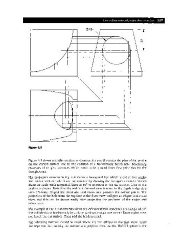
Figure 6.5
Figure 6.5 shows a similar method of construction and illustrates the plan of the profile
on the curved surface due to the addition of a horizontally bored hole. Machining
processes often give contours which need to be plotted from first principles by the
draughtsman.
The projection exercise in Fig. 6.6 shows a hexagonal bar which is cut at two angles
and with a vertical hole. Start the solution by drawing the hexagon around a 76mm
diameter circle with tangential lines at 60° to intersect at the six corners. Line in the
outline as shown. Note that the width of the end view is equal to the depth in the plan
view (76mm). Project the front and end views and position the corner points. The
projection of the hole from the top face in the front view will give an ellipse in the end
view, and this can be drawn easily after projecting the positions of the major and
minor axes.
The example in Fig. 6.7 shows two views of a cylinder which is inclined at an angle of 45°.
The cylinder is cut horizontally by a plane passing through one corner. Draw a plan view
and hatch the cut surface. Then add the hidden detail.
The following method should be used. There are two ellipses in the plan view. Draw
the large one first, modify the outline to a polyline, then use the HATCH option in the