
Page 132 - Engineering drawing from first principles using AutoCAD
P. 132
Three-dimensional projection exercises 125
cones and sphere. Examples show profiles formed by the manufacturing processes of
moulding and casting. Auxiliary projection examples illustrate cases where components
are viewed at an angle.
Plotting boundary lines
The ability to be able to project details from one view to another in order completely to
define three-dimensional objects on a two-dimensional surface is a very necessary part of
draughtsmanship. The following exercises consist of a variety of shapes and forms and
requires the draughtsman to transfer edges, corners, surfaces and points to complete
views in orthographic projection.
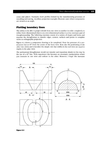
Figure 6.1 shows a component drawing to be completed. Note the presence of a con-
struction line at 45° from the corner of the front view. Note also the positioning of the
other two views and remember the simple rule that widths in the end view are equal to
depths in the plan view.
The professional draughtsman would not transfer and reposition details in this way by
the use of a 45° line. With experience this becomes an automatic manipulation where
you measure in one view and redraw in the other. However, I hope this increases
c
B
50
A-A
c
o
Figure 6.3