
Page 137 - Engineering drawing from first principles using AutoCAD
P. 137
130 Enqineerinq drawinq [rom first principles
A
L
A-A
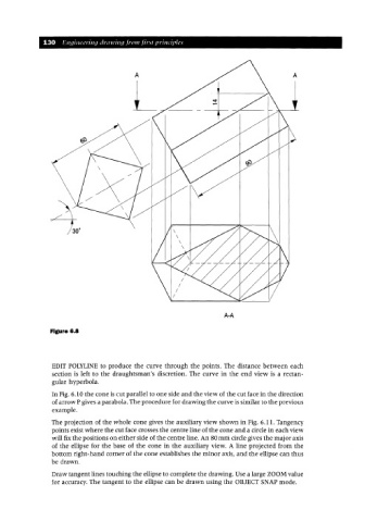
Figure 6.8
EDIT POLYLINE to produce the curve through the points. The distance between each
section is left to the draughtsman's discretion. The curve in the end view is a rectan-
gular hyperbola.
In Fig. 6.10 the cone is cut parallel to one side and the view of the cut face in the direction
of arrow P gives a parabola. The procedure for drawing the curve is similar to the previous
example.
The projection of the whole cone gives the auxiliary view shown in Fig. 6.11. Tangency
points exist where the cut face crosses the centre line of the cone and a circle in each view
will fix the positions on either side of the centre line. An 80rnm circle gives the major axis
of the ellipse for the base of the cone in the auxiliary view. A line projected from the
bottom right-hand corner of the cone establishes the minor axis, and the ellipse can thus
be drawn.
Draw tangent lines touching the ellipse to complete the drawing. Use a large ZOOMvalue
for accuracy. The tangent to the ellipse can be drawn using the OBJECT SNAP mode.