
Page 141 - Engineering drawing from first principles using AutoCAD
P. 141
134 Engineering drawinq [1"0111 first principles
-.
o
0) M
o
LO
080
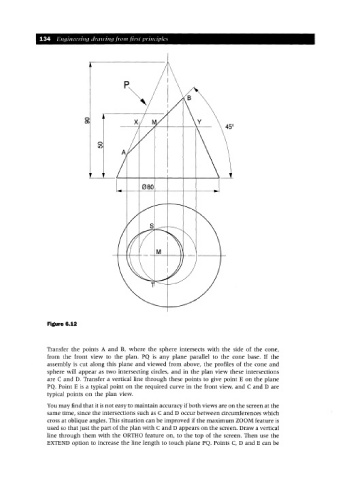
Figure 6.12
Transfer the points A and B, where the sphere intersects with the side of the cone,
from the front view to the plan. PQ is any plane parallel to the cone base. If the
assembly is cut along this plane and viewed from above, the profiles of the cone and
sphere will appear as two intersecting circles, and in the plan view these intersections
are C and D. Transfer a vertical line through these points to give point E on the plane
PQ. Point E is a typical point on the required curve in the front view, and C and Dare
typical points on the plan view.
You may find that it is not easy to maintain accuracy if both views are on the screen at the
same time, since the intersections such as C and D occur between circumferences which
cross at oblique angles. This situation can be improved if the maximum ZOOM feature is
used so that just the part of the plan with C and D appears on the screen. Draw a vertical
line through them with the ORTHO feature on, to the top of the screen. Then use the
EXTEND option to increase the line length to touch plane PQ. Points C, D and E can be