
Page 144 - Engineering drawing from first principles using AutoCAD
P. 144
Three-dimensional projection exercises 137
D E
Figure 6.15
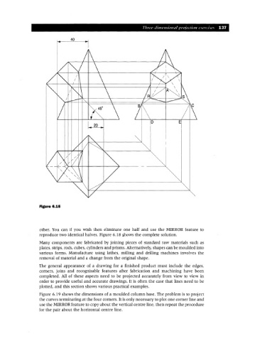
other. You can if you wish then eliminate one half and use the MIRROR feature to
reproduce two identical halves. Figure 6.18 shows the complete solution.
Many components are fabricated by joining pieces of standard raw materials such as
plates, strips, rods, cubes, cylinders and prisms. Alternatively, shapes can be moulded into
various forms. Manufacture using lathes, milling and drilling rnachines involves the
removal of material and a change from the original shape.
The general appearance of a drawing for a finished product must include the edges,
corners, joins and recognisable features after fabrication and machining have been
completed. All of these aspects need to be projected accurately from view to view in
order to provide useful and accurate drawings. It is often the case that lines need to be
plotted, and this section shows various practical examples.
Figure 6.19 shows the dimensions of a moulded column base. The problem is to project
the curves terminating at the four corners. It is only necessary to plot one corner line and
use the MIRROR feature to copy about the vertical centre line, then repeat the procedure
for the pair about the horizontal centre line.