
Page 149 - Engineering drawing from first principles using AutoCAD
P. 149
142 Engineering drawinq [rom first principles
I
I I
c/ \A
A B
I \ I
J I i\ I r.
~ -. I
I 20
'\ / "
C\ // / /tD
///V/V
- -
//~V~v
A// / v / v\ B
/ "\.
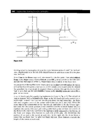
Figure 6.21
drawing would be incomplete without the curve between points A and E in the front
view, which needs to be plotted. If the FILLET feature is used then centre G in the plan
must be fixed.
Select Line in the Draw menu and take centre 0 as the first point, then select Object
Snap in the Assist menu. Choose Centre, enter OK, pick anywhere on the fillet radii
and the line will snap to centre G. Project lines from F and E to the front view.
B is any point on the top fillet curve. Draw a circle in the plan view with radius CB,then a
vertical line from the point of intersection on the outside curve to give point B 1. Repeat
the procedure for other points as required. Draw a polyline through the intersections
from A to E, then use the Edit Polyline feature in the Modify menu and select Fit to
give the best curve.
A plastic handle grip for a gardening implement is shown in Fig. 6.23. The cylindrical
form is designed with a hemispherical shape at the left-hand end and a domed finish
on the right. A metal tube is pushed into the grip along the axial centre line. The flutes
will leave irregular curves on the surface where they run out at each end. Above the
centre line is the construction for the top left side, and below it for the bottom right-
hand end. Plot the curved portions at each end then use the MIRROR feature twice to
duplicate the curves. Join each pair with parallel lines projected from the corners of
the flutes in the end view. Commence by drawing a circle tangential to the bottom of
the flutes and project this diameter to each end of the grip. This determines the
position of the end of the curves at each side. At the right side the dome leaves a
corner line as shown but the spherical finish will not. These features establish the
length of the curves at each end.