
Page 145 - Engineering drawing from first principles using AutoCAD
P. 145
138 Engineering drawinq [rom first principles
Q
o
HEXAGON
70ACROSS FLATS
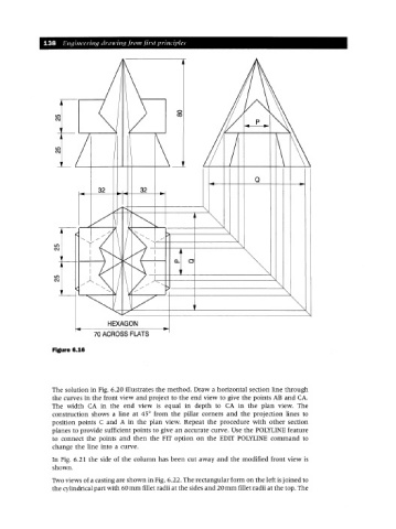
Figure 6.16
The solution in Fig. 6.20 illustrates the method. Draw a horizontal section line through
the curves in the front view and project to the end view to give the points AB and CA.
The width CA in the end view is equal in depth to CA in the plan view. The
construction shows a line at 45° from the pillar corners and the projection lines to
position points C and A in the plan view. Repeat the procedure with other section
planes to provide sufficient points to give an accurate curve. Use the POLYLINE feature
to connect the points and then the FIT option on the EDIT POLYLINE command to
change the line into a curve.
In Fig. 6.21 the side of the column has been cut away and the modified front view is
shown.
Two views of a casting are shown in Fig. 6.22. The rectangular form on the left isjoined to
the cylindrical part with 60mm fillet radii at the sides and 20mm fillet radii at the top. The