
Page 154 - Engineering drawing from first principles using AutoCAD
P. 154
Three-dimensional projection exercises 147
I· 30 ·1 - 20 ~
-
~l
~~
0
0 (Y)
C\J
,r
I. 90 "
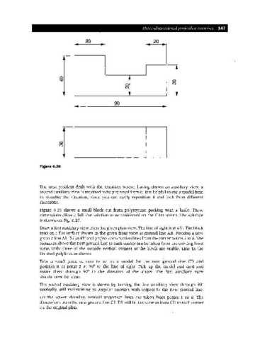
Figure 6.26
The next problem deals with the situation where, having drawn an auxiliary view, a
second auxiliary view is required to be projected from it. It is helpful to use a model here
to visualise the situation, since you can easily reposition it and look from different
directions.
Figure 6.26 shows a small block cut from polystyrene packing with a knife. These
dimensions allow a full-size solution to be positioned on the CAD screen. The solution
is shown on Fig. 6.27.
Draw a first auxiliary view from the given plan view. The line of sight is at 45°. The block
rests on a flat surface shown in the given front view as ground line AB. Position a new
ground line AI-B 1 at 45°and project construction lines from the corner points 1 to 8. The
distances above the new ground line to each corner can be taken from the existing front
view. Only three of the outside vertical corners of the block are visible. Line in the
finished polylines as shown.
Take a small piece of card to act as a model for the new ground line CD and
position it at point 2 at 90° to the line of sight. Pick up the model and card and
rotate them through 90° in the direction of the arrow. The first auxiliary view
should now be clear.
The second auxiliary view is drawn by turning the first auxiliary view through 90°
vertically, still maintaining its angular position with respect to the new ground line.
On the screen drawing, vertical projection lines are taken from points 1 to 8. The
dimensions from the new ground line CI-DI will be the same as from CDto each corner
on the original plan.