
Page 152 - Engineering drawing from first principles using AutoCAD
P. 152
Three-dimensional projection exercises 145
lines above the horizontal centre line in order to make space for a similar application to
draw the bottom right hand curve beneath the centre line. Accuracy is all-important, so
use the ORTHO and SNAPbuttons at every opportunity.
Auxiliary projections
Earlier orthographic examples were represented on the drawing sheet by projecting two
or more views at 90° to each other. A draughtsman will try to orient a component to give
the maximum amount of information to define completely all the component features,
and this consideration determines the number of principal views on the drawing. How-
ever, some details may be positioned at an angle and additional views are necessary for
clarity. Sometimes, new views of objects are required to be drawn at angles of less than
90°.
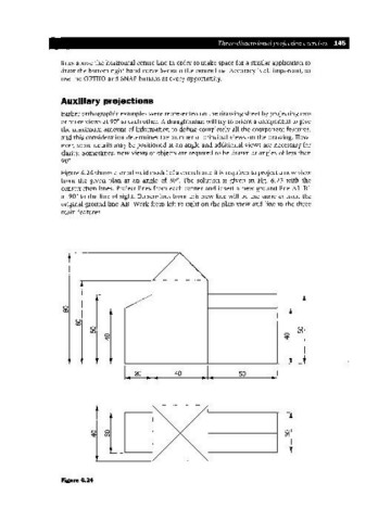
Figure 6.24 shows a small solid model of a church and it is required to project a new view
from the given plan at an angle of 30°. The solution is given in Fig. 6.25 with the
construction lines. Project lines from each corner and insert a new ground line AI-B 1
at 90° to the line of sight. Dimensions from this new line will be the same as from the
original ground line AB. Work from left to right on the plan view and line in the three
main features.
A
l
~~
Jl ~/ ~l
o
co
j~ ~l
0
(0
0 0
LO LO
0 0
~ ~
, ,r ,r
1r 1r 1r
I... 20 J... 40 J... 50
Figure 6.24