
Page 139 - Engineering drawing from first principles using AutoCAD
P. 139
132 Enqineerinq drawinq [rom first principles
Figure 6.10
Interpenetration lines between solids
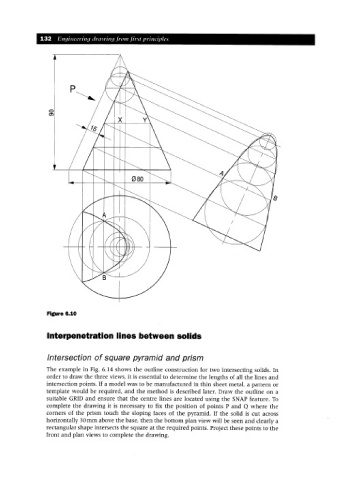
Intersection of square pyramid and prism
The example in Fig. 6.14 shows the outline construction for two intersecting solids. In
order to draw the three views, it is essential to determine the lengths of all the lines and
intersection points. If a model was to be manufactured in thin sheet metal, a pattern or
template would be required, and the method is described later. Draw the outline on a
suitable GRID and ensure that the centre lines are located using the SNAP feature. To
complete the drawing it is necessary to fix the position of points P and Q where the
corners of the prism touch the sloping faces of the pyramid. If the solid is cut across
horizontally 30mm above the base, then the bottom plan view will be seen and clearly a
rectangular shape intersects the square at the required points. Project these points to the
front and plan views to complete the drawing.